Fig.1 Bulb folder
Fig.2 HID bulb dimension
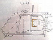
Fig.3 Light cut-out sheet (Red line) for low beam
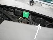
Fig.4 Bulb cover
Fig.5 My choosen set
The original Citroen XM main beam is so dark even in clear night that many XM owners confessed that they have experienced to check if the light is really “On” and soon realized it is "On”, then back to reality with disappointment.
My previous silver XM-X was not an exception, main beam was very dark, so I was told that she would hardly pass the automobile safety inspection. Driving my XM in rain was almost a fear, so some owners have done HID conversion for safety.
I myself have also been interested in HID conversion.
But I could not move ahead because of the following concern.
1. HID conversion kit is usually very expensive. Price range of $300 to $500
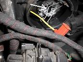
2. HID conversion requires bulb holder modification (See Fig. 1)
3. Long bulb Dimension (a) may touch the transparent light cut-out sheet developed by Valeo specially for Citroen XM (See Fig. 2 and 3)
4. Bulb dimension (b) should also be short not to touch bulb cover. (See Fig. 2 and 4)
5. HID conversion requires to drill a hole in plastic bulb cover
6. Water and dust tight sealing for the driller hole required
7. Ballast (voltage transformer) mounting work to chassis required
8. None of above work is a simple DIY work, so many XM owners reluctantly ask garage for costly professional work
[How I then came to consider HID conversion to my XM ?]
I was contacted and was informed by a Xm freak Mako san (“san” is a Japanese word for “Mr.”) that he found an inexpensive HID DIY kit for his Citroen XM at Yahoo auction and he succeeded in fitting the kit with perfect result by himself.
I had heard that some XM owner bought HID kit for around $100 (cheap !) at Yahoo auction, and tried DIY fit by themselves but mostly failed, so ended up regretfully with an expensive garage fit.
To complete conversion work by myself to minimize expenditure, I had to find out resolution for the above my concern 2 to 8.
Fortunately, the HID DIY kit Mako san introduced to me eliminated above all my concern.
1. Extremely low price : Less than $40 Wow !
2. No modification required to the bulb holder
3. No interference with the transparent light cut-out sheet in headlight assembly
4. No interference with bulb cap
6. Water and dust tight sealing rubbers are included in the kit
7. Ballast attachment to chassis using double-faced adhesive tape
They are all good news to me.
To drill a hole in plastic bulb cap (concern No.5) was the only remaining concern, but Mako san explained me that no special tool like a electric drill was required but just a large knife readily available at home.
All his encouraging suggestions cheered me up.
Another Xm freak M san read my blog and was so encouraged that he fitted HID himself with additional relays and so on, but ended up with unsuccessful result with bulb flickers---.
I came across with many unsuccessful story, but single success story of Mako san’s HID conversion was more than enough for me to go ahead with HID conversion.
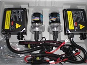
Fig.6 Kit overview
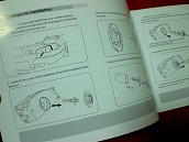
Fig.7 Attached installation manual
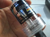
Fig.8 HID Protection cover
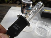
Fig.9 HID bulb
There are so many HID bulbs available in market. So, you first have to specify bulb type, brightness (W), and color temperature (K).
As for bulb type, you should follow the original bulb type i.e. H1 bulb, so there is no room to choose other types.
As for brightness, you generally have two options. 35W or 55W. MAKO san recommended 35W. Higher the “W” number, brighter the light. And brighter is better naturally, So, my first choice was 55W and I carefully compared it for dimensions with 35W from the same supplier. I then found out that 55W bulb was too long. I remembered my concern No. 3 and 4, and I gave up 55W.
As for color temperature. I followed Mako san’s path i.e. 6000K. It is said that color temperature has nothing to do with brightness, but with color tone. Higher color temperature makes light to look more bluish. Color temperature at around 6000K can offer a color tone close to white or a bit bluish, which I prefered. But I was not sure whether the 6000K HID bulb met the automobile safety inspection, so I worried a bit. It would have been safer if I had chosen 5000K, but 5000K bulb was not available. This was the reason why I purchased 6000K bulb.
I maybe was greedy, because I started looking for even less expensive kit than the one Mako san purchased. I continued search for even less expensive conversion kit for H1 with 35W and 6000K HID bulb.
There were less expensive HID kits at Yahoo auction.
Auction bid price of some HID kits was around $20 and I could find even far less expensive kits with a bid price of almost a cent !!
Mako san’s recommended supplier was offering attractive flat postage of $10 for all over Japan, but less expensive HID kit supplier’s postage was always more expensive than $30. No reason to choose them having no proof for perfect fit and operation.
Also their warranty was for a limited three day period which was less attractive comparing with one week warranty offered by Mako san’s supplier.
Package pictures of these low price kits looked all right, but who knew that pictures told the truth. So I decided to buy the one Mako san recommended. Kits at lower price would have potential risk and drawback.
Furthermore, many suppliers only accepted cash on delivery (COD), but Mako san’s supplier accepted electric payment by Internet so called Yahoo-easy-payment with credit cards or electric bank transfer. Advantage of the Yahoo-easy-payment is that you can collect points from Yahoo for each transaction. I collected a lot of points at that time,
so I could make full payment of 4998 JPY without money but just with the Yahoo points.
3760 JPY (Kit) + 188 JPY (Tax) + 1050 JPY (postage) = 4998 JPY.
Official name of the kit was “ The Latest Digital HID Kit H1/6000 with EMI with 35W ”. Seller ID was “horieshop2009”.
“ Cheap staff is prone to break easily.”
If this kit broke then I simply would purchase the same one again. Even if it broke, I could simply change them back to the original Halogen bulbs. Very unlikely that whole kit broke and became useless.
If this happened, I needed to buy only broken parts. i.e. burners or ballast for $20 each.
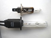
Fig.10 Length difference H1 and HID
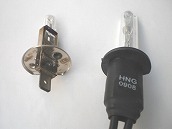
Fig.11 Same bulb seat shape
Luminous device filled with Xenon gas to emit light under high voltage was carefully packed in protective plastic and arrived.
HID bulb was much longer than I expected, so I became anxious about interference with other parts.
But I soon became convinced, because Mako san had already proved perfect fit of this kit to his Xm.
According to the instruction manual attached to the kit, HID bulb had the following advantages over the original H1 bulb:
Electricity consumption: more than 40% less Brightness: more than triple more Life: 2500 hours or more (400 hours for Halogen)
Big size difference in length between H1 and HID bulb can be seen in Fig.10 (H1;Up, HID;below)
Also please be noted that both bulbs have the exact same bulb seat shape.
My concern No.2 now became clear.
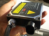
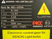
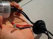
Fig.12,13 Ballast
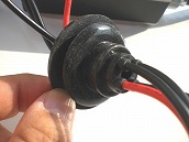
Fig.14 Dust tight rubber sleeve
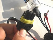
Fig.15 Water proof harnesses
Water and dust tight rubber sleeves were included in the kit. (See Fig 14)
Wire harnesses were water proof type. (See Fig. 15).
Kit overall view can be seen in Fig,6
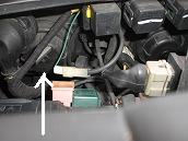
Fig.16 Left bulb cover seen from back
It is advisable to do below preparation work before kit arrival.
“Preparation 1 Drill a hole in bulb cover.(See Fig. 17)”
Drill a hole in plastic light cap for wires passing through.
HID conversion was for low beam, so remove the low beam plastic cover located on outer side of the vehicle. Plastic cap was threaded, so undo the cap anti-clockwise. The Fig. 4 shows the right hand side head light bulb seen from back.
Fig, 16 shows the left hand side head bulb seen from back. Arrow shows the low beam bulb you need to reach, and you will have great difficulty to reach (Blame Citroen designers !!).
In my case, this cover was too tight to turn, but finally I could make it with a lot of effort. My right hand grip is 42 KG or so for your reference. Maybe French has stronger hand grip ?
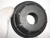
Fig.17 Drill a hole in bulb cover
Another Xm freak Sal san did HID conversion in the past and his Xm was recently written off. So, he gave me the redundant bulb covers having hole for my conversion
work. Sal san also kindly gave me a Hydractive ECU with a big bargain.
Taking this opportunity, I would express my gratitude to his kindness.
Thanks a lot Sal san !
I still do not know how Sal san made a hole in this cover, but Mako san told me that he used a rather large knife at home as previously explained.
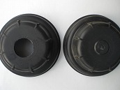
Fig.18 With and without hole
For dust tight purpose, it is advisable to close hole with adhesive tape.
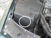
Fig. 19 Best Location for right
side ballast
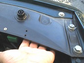
Fig.20 Serching another location
Examine the location of the ballasts. I think that it is better to investigate location before
kit arrives.
The kit contained two ballasts for both side HID bulb operation. So, needed to examine the location for both right and left sides of the vehicle.
The recommended location of right side ballast I heard from another Xm freak I came to know via MIXI (“MIXI” is a most popular Member Communication Site in Japan) is shown on circle (See Fig. 19).
He attached the ballast to ECU box using screws.
ECU box is made of plastic, so you can easily drill holes to fix ballast with screws.
But I did not like to drill holes to ECU box. I first thought to use an adhesive tape instead. But considering heavy ballast, I gave up with this idea and revisited other locations.
My palm shows the other possible location (See Fig. 20). This location offered enough area for the ballast to accommodate, but the surface was not smooth, so difficult to hold the ballast firmly.
Double sided adhesive tape was obviously useless, and fixing with screws seemed to be difficult.
The ballast was fairly heavy, so it might drop. I should not fight against the principle in physics “the gravitational force”. So, I gave up with this location, too.
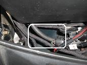
Fig.21 Anothe location for right
side
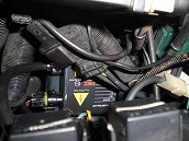
Fig.22 Location for left side (Picture taken after installation)
This location was hidden by many wires running over it, so this was why I did not notice. But there was surely enough space for a ballast.
This space(Fig.21) served to drain water coming from gap between bonnet and wing panel.
No pictures were available, but there were two water drain holes hidden under wires shown in white square (See Fig. 21), and there was another small drain hole around the head light assembly.
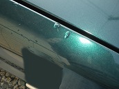
Fig.23 Drop rain in the slit
I continued my search for better location to wipe out this concern the other day. (Click here , although in Japanese, you can find better location)
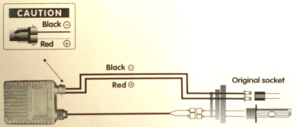
Fig.24 How to connect (Click to
see in larger size)
Upon receipt of the kit, I strongly recommend to carry out a performance test without delay. The kit carried guarantee for the initial defect for a period of a week from the date of arrival. This was not a “Made in Japan” product, so it was worth to check for the operation. I strongly recommend you to conduct a test within a week before guarantee runs out !!
In my case, I did specify delivery day of Friday, so that I could do the test on the following day during the weekend i.e. Saturday without rush but with composure.
To conduct a test, first remove the H1 bulb from your car. Next, connect the wire from vehicle to the ballast, and connect the other wire of this ballast to HID bulb respectively.
(Important!!)
All work under bonnet to be done when engine is cool to prevent possible skin burn.
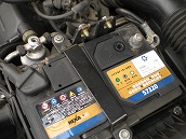
Fig.25 Disconnect for safety
Instruction manual did not call for this, but I spotted this somewhere before.
From my past experience for safety, I did disconnect negative lead first.
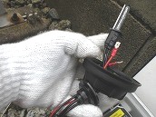
Fig.26 No touch with bare hand
Remove protective cap, then push HID burner through bulb cap hole.
(Important!!)
Never !! touch the glass surface of HID bulb with bare hand.
This is the same care required to handle Halogen bulb.
If you touch bulb surface with bare hand, you put human grease on bulb glass surface.
When light gets on, then bulb surface gets very hot, so human grease on bulb surface burns and creates hot spot on bulb leading to glass fracture,
To prevent this glass break after installation may happen, I always wear glove.
Better be prepared.
I would recommend to wear a glove with fine texture.
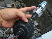
Fig.27 Put sleeve onto bulb cover
Put burner protection cover onto HID bulb, then put this sleeve onto bulb cover.
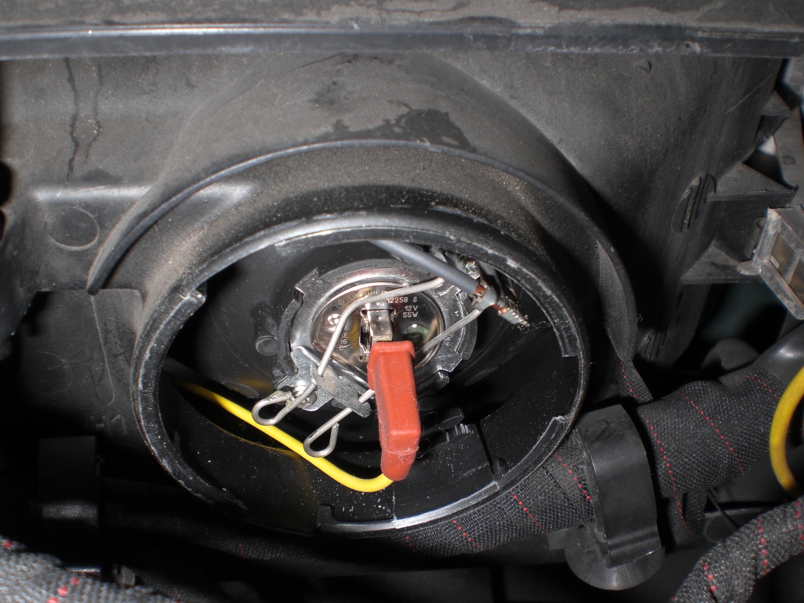
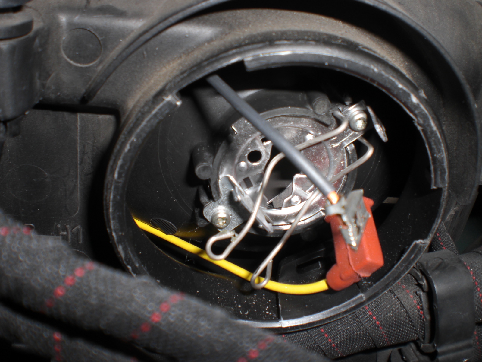
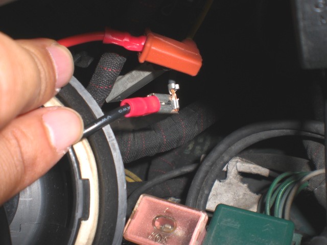
Fig.28 Disconnect red connector
white arrowed ,then release
retaining spring yellow arrowed
(Click to see in larger size)
You can see the red harness (white arrowed) when cap is removed.
Disconnect it. (See Fig. 28)
5. Remove the retaining spring.
Release the spring clip. Compress the spring (yellow arrowed) while pushing it toward the bulb holder. (See Fig. 28)
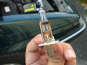
Fig. 29 Detach H1 bulb succsessfully
When spring is released, H1 bulb connected to red harness can be removed.
Fig,30 Whre connect black wire?
According to the instruction manual (See Fig.24), red and black wires from H1 bulb were to be connected to the red and black harness originally connected to H1 bulb.
First I connected the red wire to red harness from H1 bulb. Then the black wire...whoops, no connection for black wire---where should it go ?
I could not find black harness. Where was it ? Did I have to connect to body earth ?
I asked this question on the Avant-garde square page of my website. M san explained me that it should get connected to the one shown in blue arrow on the picture above.
(See Blue Arrow in Fig. 28)

Fig.31 Disconnect black harness
(Click to enlarge)
I pulled out black harness with pliers. (See Blue Arrow in Fig. 28)
I have removed H1 bulbs many times for H1 bulb replacement work, but I have never noticed this minus terminal at all! This terminal was invisible when seen from above during routine bulb replacement work.
I could have never noticed it for the rest of my life unless M san taught it to me.
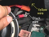
Fig.32 Connect wires from HID
bulb to harnesses from the vehicle.
(Click to enlarge)
Connect the red wire from HID bulb to yellow wire with red harness from the vehicle, also connect the black wire with red sleeve to the black wire from the vehicle.
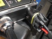
Fig.33 Connect harness to
ballast
Connect the plug into the ballast (at right side). Be careful about polarity!
Indication of minus (upward) is the side where black wire should be connected.
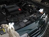
Fig.34 Turn light on for test
(On mouse to see close-up)
Bulbs successfully lit.
HID bulb becomes so hot that protective cover may melt. It would be better to remove the protective plastic cover completely before switch on.
It was OK for just 10 seconds or so, but never more than that.
Turn off the light switch, and stop the engine, too.
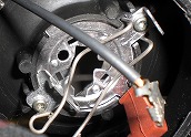
Fig.35 Ihsert HID bulb to this
hole
1. Insert HID bulb, retain by spring, close cap.
It is almost close to finish.
Wait until hot HID bulb becomes cool enough to be able to hold with hand. Insert a HID bulb into a bulb mount.
First, I did it from the right side head light.
But, it was so tough that I struggled a lot. I was in a rush and was impatient to take pictures, because it was close to sunset and getting darker and darker every minute.
HID bulb diameter was too close to the mount bracket hole, so no play for adjustment but just fit, or the mount bracket hole dimension of my Xm maybe was different and smaller than that of Mako san’s Xm ?
I almost gave up. I was about to give up my last trial and to remove the mount bracket to enlarge the hole. But wait --- Why thoughtful Mako san never mentioned about this difficulty?
I was puzzled. But how can I make it? I was impatient to die.
I continued my trial by rotating burner, angle and so on aimlessly----, then all of sudden burner fit in !!!
I was so happy as to kneel down. It was a struggle for a quarter an hour or so, but I felt as if almost hours of struggle.
You can have only very limited room to work. Work by my hand was invisible, so my shoulders were getting stiffer.... like struggling with a wire puzzle.
After all work was complete, I carefully read Mako san’s blog again and found that Mako san had written about this difficulty.
He was saying that "to ease the fitting difficulty of right hand side HID bulb, I bent the bulb mount bracket a bit using pliers."
I should have read his blog carefully.
When I saw Mako san’s picture, it looked like that he might have even removed the bulb bracket to bend.
I was amazed. How did he accomplish this bending work ? He might have been forced to remove the whole head light assembly from his Xm.
On the contrary, left-hand bulb fit in bracket perfect just by a snap without irritation.
This was exactly what Mako san wrote. I would believe that right and left hand side bracket had slightly different shape.
I would recommend you to start with left hand side first.
After securing right-hand HID bulb for perfect fit, lock the spring clip, then tighten the bulb cover.
How to deal with entangled wires? I just push them into cap.
I was sure that short circuit would not happen, as positive harnesses was protected.
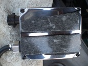
Fig.36 Attached rubber pad for water proof.
Ballasts surface should be free from grease, so surface was cleaned using cleaner.
The ballast is waterproof design, but it is recommended to prevent contact with water, A 5 mm thick rubber pad was placed on the flat surface using double-sided adhesive tape.
The rubber pad blocked drain holes and double-sided adhesive tape was exposed to water. I still can not tell how long this arrangement would last.
Let me see as it is for the time being.
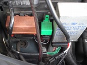
Fig.37 A little difficult to dettach
the cover of ECU BOX.
I was thinking that the best location for ballast was near ECU box, but I could not make it because the ballast was too thick. So, I was forced to remove the cover of ECU box. It was hard to remove this cover. Shape of cover at lower part was different from the one of early XM model with Hydractive I.
The biggest difference was a silver color module which was not attached to early XM model.
I didn't know the function of this item, but this was a large unit with many wires making the lid stiff from moving. I disconnected wires between ballast and bulb to make my work easier.
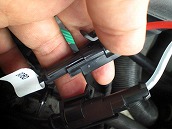
Fig.38 White lavel for red wire.
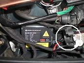
Fig.39 Temorally disconnected.
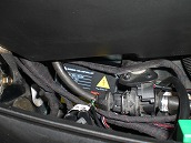
Fig.40 Installation ballast on lef
t hand side.
Do not remove this cover, or you will suffer greatly.
Fig.41 Installation ballast on right
hand side.
Do not locate the ballast on the drain hole. There was a slight gap making a firm ballast fix using double-faced adhesive difficult. Perfect fit was not possible, so I decided to find out a better solution later.
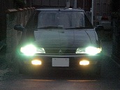
Fig.42 See difference sight from
HID to Halogen by your mouse on the picture.
Light on test finally.
At dusk, it looked bluish. Significant difference in color from Halogen fog light.
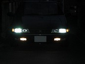
Fig.43 HID low-beam head light
It was impossible to show the difference with pictures by digital camera. None of digital camera picture mode showed the real difference unfortunately. Browny for Halogen bulb and bluish for HID.
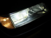
Fig.44 HID looks very cool.
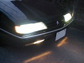
Fig.45 buluish whitle color
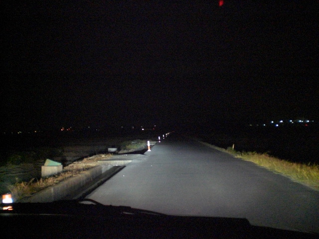
Fig.46 Click to enlarge HID sight
By click you can enlarge the picture, you can see eight or more poles on left-hand side of the road.
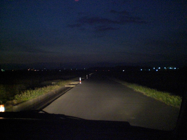
Fig.47 Click to enlarge Halogen
sight
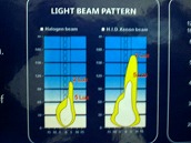
Fig.48 Difference of protection
angle
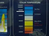
Fig.49 Difference of color
temperature
kit package. (See Fig. 48)
This figure shows HID has brighter and wider projection. It is consistent with my experience in the picture above.
White band is 6000K in color temperature. Halogen bulb appears to be around 3200K.
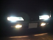
Fig.50 HID for your safety of
night driving.
HID bulb is 35W which is lower than 55W Halogen, however I feel brighter projection by HID.
The field of vision is lit white, or a bit bluish. I can obtain brightness making night drive much easier and safer than with normal Halogen thanks to the higher color temperature.
I had many occasions I could spot approaching pedestrians towards me much earlier than before.
There are some websites explaining differences of visions in relation to color temperature.
I was very satisfied with this HID conversion kit quality and its result.
I would herewith express my gratitude to Mako san who recommended this product and to M san who supported me with various advices.
Please find a sequel of altering the ballast location.